 Builds An Anodizer
Note: This is not a demonstration of good practices, nor how to build a serious production anodizer.
It's just a fun project for the electrically adept would-be titanium artist. It does work; I had one like this back in the
early 1980's. See the bottom of this page for the sort of problems you may encounter using this gizmo.
It is possible to later adapt this to more serious use by replacing the dimmer with a varioable transformer (e.g: Variac) and the
light bulbs with proper power resistors.
|
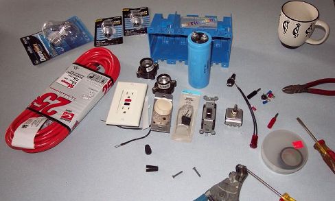
Here's the basic parts. I used a 4-gang electrical box to contain all the parts.
The extension cord is a cheap source of a plug and wires.
I'd just drained my Kokopelli mug of coffee before beginning. |
 |
| First, we cut the cord, run the wire into the box, and run power to the GFCI and through it to the dimmer switch. | 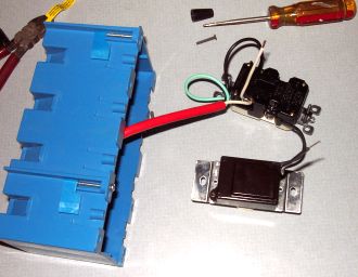 |
| "Tin" the leads before attaching to the bridge rectifier. Then solder the leads. Note the shrink-tubing I'd slipped over the wires before soldering. I shrunk it with a lighter. | 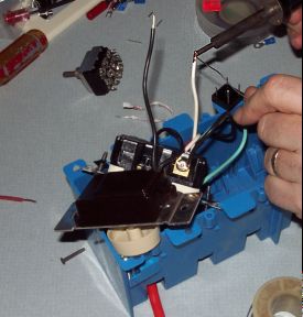 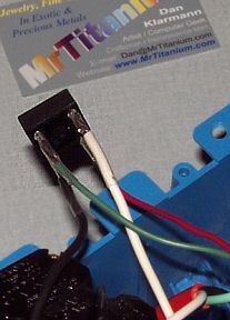 |
| The rectifier tucks neatly below/behind the GFCI. | 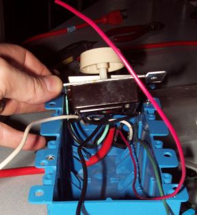 |
|
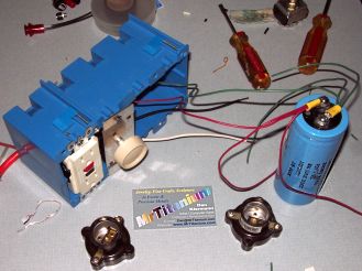
Attach wires to the capacitor. I found a 250volt, 2,200mfd for $3.50 at a scrounger's shop.
I used loop connectors and ganged 3 wires into each one, soldering them into the connector,
but trusting screws to hold them to the cap.
Note that this cap fits neatly behind the other components in this box. And I screw the light fixtures to the top. |
 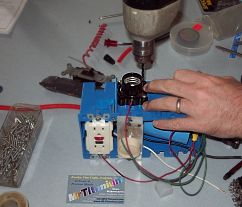 |
Light fixtures? Well, 100w power resistors will do a better job, but light bulbs are easy to come by.
Note the banana jacks I put through the side, as well. And now to solder in the 3pdt switch, with center off and momentary positions. |
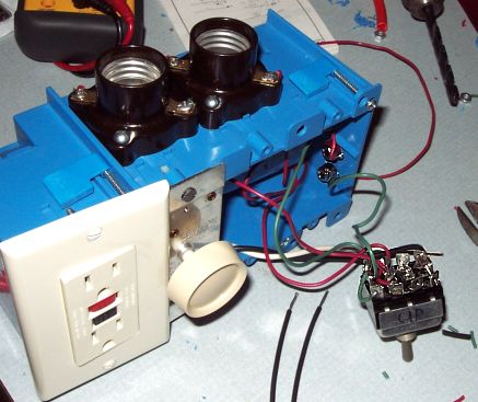 |
| This switch is actually a 4PDT, but I'm ignoring the spare set of Poles. I want to have both the + and - sides disconnected when off, and to have an indicator light shine when it's either in the ON or MOMENTARY positions. | 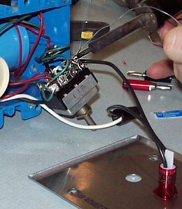 |
| So, here's an exploded view, showing all the parts and giving an idea of how they interconnect. | 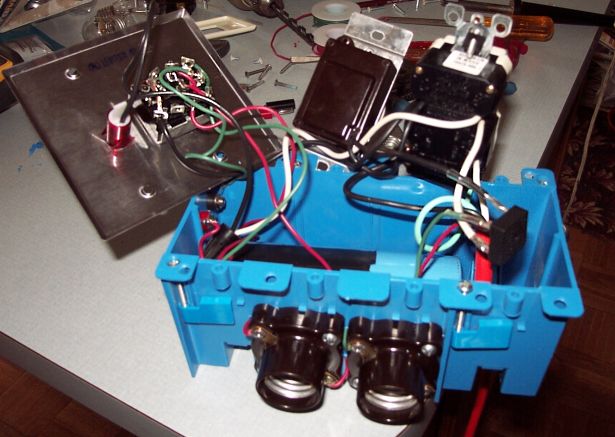 |
|
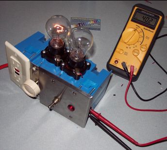
Finally, showing the thing with a bit of power on, the indicator light on, and the dimmer-load-light aglow.
Click here to see the page listing components, options, cautions, and instructions. |
 |
As I promised at the top of the page, here is what is wrong with this design and how to fix it:
- Light bulbs are fragile, and the load light gets annoyingly bright at higher voltages. Power resistors are preferable.
- Dimmer switches are very susceptible to small variations in line voltage, especially in the important 15-40 volt output range
- Dimmer switches can get confused by the capacitor load, and start pulsing and burn themselves out. Always make sure the dimmer is turned down before turning on, and then turn up quickly to a stable brightness, before backing it down to the voltage desired.
- A small variable transformer costs 10 times more than a dimmer, but is ever-so-much nicer for the user.